Home › Forums › General Discussion Forum › Graham escapement
- This topic is empty.
-
AuthorPosts
-
January 9, 2014 at 1:30 am #48790
I am working on a srping driven Viennese regulator having a Graham dead-beat escapement.
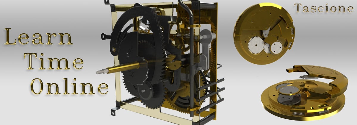
The impuls faces of the pallets are a bit worn (see attached pictures) and I was wondering what to do. I presume that polishing them would be in order, but I am reluctant to teach the pallets because I fear that I would alter the angles and or distances.
The clock was not ticking, but I don’t know if this was due to wear on the pallets or just friction.
I am cleaning the clock and replacing the mainspring.
This is the first time I work on a Graham escapement, so any thoughts on this are welcome!Jan

 January 9, 2014 at 6:34 am #55079
Hey Jan, I would definitely do something there, these are made to be adjusted for lock and drop, ie the extra length and the clamping system. alot of times they are cut at the same angle on both ends of the pallet and you can flip them over. Be sure to measure the original distance as that will get you close to where you want to be. You will still want to recheck it with the escape wheel between the plates for proper lock and drop. Do you have any books on escapements? Also if you were to polish and burnish the original grooved ends, depending on the tools you have, try clamping the verge in a way that will allow you to be accurate and steady while filing/polishing/burnishing (use of imagination required
") ). Remember it is easier to take more off than add more on. Looks like a fun project, have a great day, WilliamJanuary 9, 2014 at 7:36 am #55080
). Remember it is easier to take more off than add more on. Looks like a fun project, have a great day, WilliamJanuary 9, 2014 at 7:36 am #55080Thanks William,
I was quite sure that I had to do something here. The problem I see is that it is easy to change the angle of the impulse face or the width between the pallets.
I don’t have a book specifically on escapements. I do have “De Carle: practical clock repair”, but it does not have an explanation on how to adjust a Graham escapement. Can you recommend some literature?
The pallets are not made such that I can flip them over, so I think that filing, polishing and burnishing is about the only way to go.Jan
January 9, 2014 at 8:33 am #55081Hi Jan,
You are correct about being careful not to change the lift angles. Fortunately you have the perfect machine for doing the job. Your Taig lathe will work beautifully for this. If you have a fine grinding wheel or a mandrel that you can glue emery paper onto that will fit in the spindle of your lathe you should be good to go. The idea is to rig up a small fixture that will allow you to do one of two things. You can remove one pallet at a time and clamp it onto your cross slide vise or tool holder and then under high magnification bring the impulse face up to the wheel face to align it up with the existing angle. Or if space allows for clearance you can make a small plate with a close fit hole drilled through it for the anchor arbor to fit through and then clamp this simple fixture into the holder on your cross slide. You can then rotate the anchor until it matches perfectly the existing angle. By adjusting between your cross slide travel and rotating the arbor in the plate hole you should be able to quickly line it up. After everything is set up you can feed the cross slide into the wheel for grinding. If you set it up where it is grinding cross grain to normal sliding direction of the escape teeth then it’s important to polish out any scratches in the same direction as the escape teeth action. Polishing can be done without the use of the fixture set up as very little material will be removed during the final polish.
As William pointed out it’s a good idea to take a few measurements that will help you with final escapement adjustments.
I have to run to town for a little bit so I’m typing this on the fly so I’m most likely skipping some important tips that can be given so I hope this makes sense!
If you have any questions about what I’ve written here please let me know. I should be back at the computer within a couple of hours Jan.
Adios for now,
BobJanuary 9, 2014 at 8:55 am #55082Hey Jan, In DeCarles book look at page 209 for adjustments. I have a good little book called “the escapements” (their action, construction and proportion) by F.J. Britton, a small paperback with several types of escapements described. I am sure there are many other books out there on the subject and would go into great detail. If you had a solid anchor?,(the name escapes me) then yes if you do any polishing it will change the lock and drop and adjustments are difficult. this one you have has been made to easily adjust for that by sliding the pallets thru the slots when the clamp is loosened. when adjusted they will stay at the correct radial line from the center of the anchor arbor to provide the proper lock and drop. be slow and careful when polishing the impulse faces with light pressure and checking often so as not to change the angle of the impulse face. the book I mentioned gives the formula to draw the escapement on paper. I found doing this gave me a better understanding of the theory. I have a PDF that is very informative BUT I do not know how to put it up or even if I should, hopefully Bob is not napping in the sunny warm weather and can help us out on that. William
January 9, 2014 at 8:01 pm #55083Jan,
Is that path in the middle of the impulse face supposed to be there or was it worn in from the excape wheel teeth? If it was worn in by the excape wheel then the angle is different than the rest of the impulse face. A clock or a watch escape mechanism is the same as any cam pushing against a cam follower. The angle of the cam follower (impulse face) will definately affect the transfer of force from the escape tooth to the pendilum.
davidJanuary 9, 2014 at 11:26 pm #55084Thanks Bob for your help. I will see how I can get the pallets mounted on my lathe and find a way to grind them without changing the impuls angle. Maybe I will come back for more help while doing this
William, I read De Carlo’s description, but I don’t feel that it helps much in the way of explaining how to adjust the pallets.
Thanks for the info on your book, I will see if I can find a good book on escapements.
Maybe you can send the pdf to my email: [email protected].Randy, I had no doubt that it would be better to correct the impulse faces. I was just hesitating because a worn impulse face is probably better than a wrong impulse angle
, but I feel more comfortable now with the hints given by Bob. I just would like to be more confident that I can get the pallets back in their places with a proper lock and drop.Jan
January 10, 2014 at 10:50 pm #55085Just realised that I addressed the last paragraph of my previous post to Randy where I meant David 😳 . Don’t know how I did this, probably too occupied with what I am doing rather than paying attention to what I am writing. I appologize to both David and Randy.
Here is a picture of the setup in my Taig lathe. The pallets are now grinded, I will polish them and try to install with correct lock and drop.
Jan
 January 11, 2014 at 6:44 am #55086
Jan,
My perspective is NOT from someone who knows about clocks as I never worked on one. The groove looked as if it was not supposed to be there but I did not know for sure. Hopefully you measured the distances from the clamp block to the impulse units before removing them. The impulse angles can be duplicated with mathematics or by physically drawing the radius of the part and measuring off of a tangent line to that circle. This is only what I would do but there may be other ways to nail the angle down.
davidJanuary 11, 2014 at 6:46 am #55087Thanks for posting the pic. Jan.
That Taig is nice. You were able to clamp right onto the table rather than making the plate. Good thinking!
I want to mention here for anyone reading this that may want to use their lathe that it’s important that the flat surface of the wheel or grinding disk is used and not the outside edge of the wheel. The outside edge will transfer the wheels radius into the lifting angle of the pallet when grinding. The picture might give the impression that the pallet closest to the camera was ground using the wheels edge but a closer look shows the other pallet just touching the flat surface of the wheel.
Nice work Jan!
Please let us know how you did the polishing.
Thanks,
BobJanuary 11, 2014 at 7:01 am #55088Hi David,
You must have been posting at the same time as I was a few minutes ago.
Yes when in doubt about the angle it’s pretty simple to check it using the half anchor radius/tangent method. Will need to determine the original lift angle first though. Not always 2 deg. as often believed.
Not a bad idea knowing exactly what the angle was originally in case someone in the past changed it.
In most cases just picking up the angle under high magnification by bringing it up against the flat surface of the wheel will get you dead on.
BobJanuary 11, 2014 at 7:15 am #55089Thanks Bob,
the Taig is used here with a headstock with a WW-spindle and draw bar. Thanks also for pointing out that I was using the side of the grinding wheel, which I should have mentioned. I realized later that the picture might be deceiving.
I did polish the impulse faces using emery sticks (very fine grain) and finally 3M lapping film (3 micron). They now have a mirror finish
") .
.I mounted the escape wheel and anchor and tested drop and lock and so far it seems ok to my (untrained) eye
.Jan
January 11, 2014 at 7:21 am #55090Thanks David for your advice. I was reading up on the geometry of a Graham escapement and yes it is possible to determine the impulse angle. I did not do that however and assumed that the existing angle is correct, which is the most likely case unless someone even more clueless than I am ruined it before
Jan
January 11, 2014 at 7:49 am #55091Hi Jan and David,
I’m anxious to hear how the clock performs after you have completed it and have it up and running. Yes Jan I agree with you about the angle most likely being correct. There has been a lot of discussion in the clock communities over the years covering this topic. Some believe that it’s absolutely necessary to determine the angle and then grind to this original angle. I don’t fully agree with that belief. Unless the escape wheel teeth have been embedded with diamond dust or carbides that wear that you had to grind out of those hardened pallets took MANY years to wear into those faces. That would mean that the clock must have been running fairly well to have run all of those years. I’m certain there are cases that an angle may have been altered because I’ve personally dealt with those alterations but for grooves as deep as those in your pallets my feeling would be they are most likely correct.Please do let us know how things go Jan!
BobJanuary 11, 2014 at 9:59 pm #55092Jan,
Bob pointed out to me that it may have taken 50 to 100 years to wear in that groove. That being the case, the initial angle was certainly time tested and there would be no reason to change it. I thought of another way to duplicate the angle on a part with a radius on the way to work this morning. After measuring the distance of the old part from the clamp, pull the part out and lay it on a piece of paper. Then carefully trace the outline of the part on to the paper and cut out the tracing. Next, place the tracing on top of the part and slide it back to the place you wish to grind back. Next scribe a line on to the part following the traced angle and grind to the line. Place the reground part back into the clamp at the previously measured distance.
david -
AuthorPosts
- You must be logged in to reply to this topic.